Das Race
The 12th of December 2021, a charity event called Das Race is taking place in the BMW Arena, Munich, Germany.
Das Race is a car soccer competition similar to Rocket League, the difference being that the cars and the ball are real life objects controlled by different celebrities and esport players through the internet. For this occurence, I was tasked of preparing the cars, the ball, the infrastructure, and managing the different actors of this event.
Preparation of the cars
The volume variation is done numerically by using a time of flight sensor connected to an STM32 board. The distance information is sent to the STM32 and we can program the output volume accordingly.
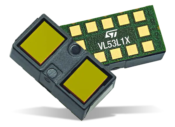
The time of flight used is a VL53L1A1, it works by sending and receiving an infrared laser, it allows to get a distance in nanometers stored in 32 bits. Then the STM32 processes the 32 bits distance and outputs a value between 0 and 2048 that we send to the Digital Analog Converter (DAC) to convert the numeric value into a voltage that will arrive at the gate of the transistor (2N3820).
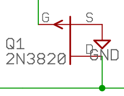
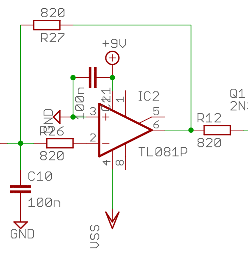
According to the gate voltage, the output will vary between 0V and 9V and it will power the speaker. The loudness of the speaker depending on the input voltage, the volume of the speaker varies from mute to full volume. We originally wanted to wire the STM32 to the audio amplifier but doing so would saturate the sound since we’re lowering the maximum voltage of the output instead of lowering the input.
We encountered several problems with the Time-of-flight sensor, but they were all related to the fact that it’s a proprietary sensor and board, and they were not made for one another. For example, the library is not made for our STM32 board. The code is made for Cortex M4 instead of our Cortex M3, so we had a different register than the datasheet. So, when we wanted to access a certain register, we had to make a loop that would check every address. We also had to edit some files to make the drivers compatible with the time-of-flight API.
Preparation of the infrastructure
The frequency variation, contrary to the volume variation, is done analogically. The system is made of two oscillators : a fixed one and a variable one. The variable one is controlled by the hand of the player which acts as a variable capacitor relative to the distance of the hand.
The frequency variation works this way :
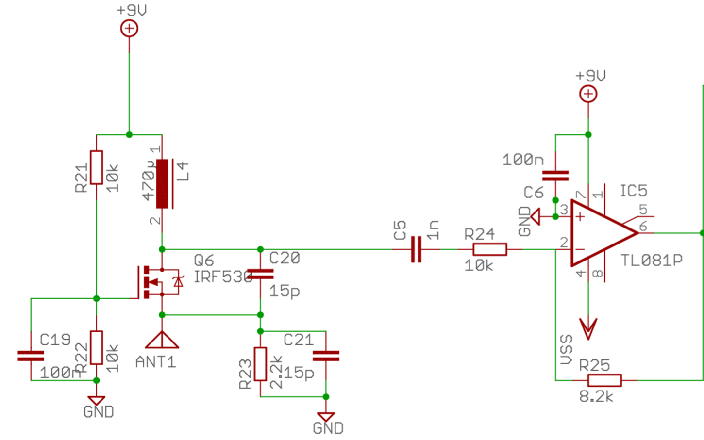
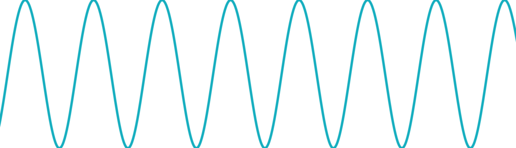
We have two oscillators linked to two amplifiers. A fixed oscillator and a variable one with an antenna. The fixed oscillator emits a 520kHz sinewave whereas the variable one can emit a sinewave between 500kHz and 520kHz. The hand acts as a capacitor and its movement around the instrument is caught by the antenna and changes the frequency of the oscillator.
We used several oscillator architectures, including a Colpitts oscillator, made from resistors, capacitors and inductors, but we didn’t have a satisfying enough sine. So we modified the Colpitts one empirically to get what we wanted.
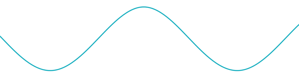
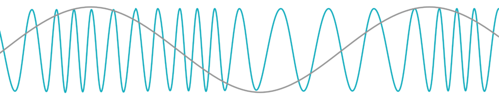
Once we have the modulated signal with the envelope being equal to the difference between the fixed signal and the variable signal, we extract said envelope thanks to an active low-pass filter which removes the carrier wave’s signal to keep only the envelope.
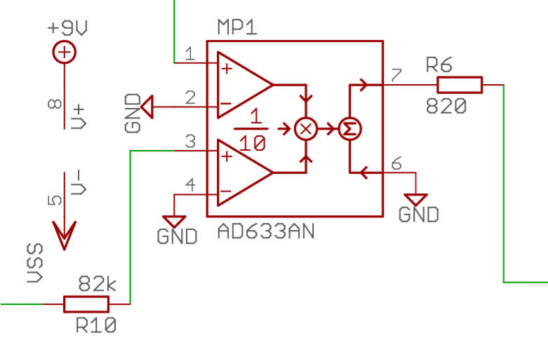
We then modulate the two signals in order to substract the two frequencies by sending them to an analog multiplier. The fixed oscillator emitting 520kHz minus a variable one emitting between 500kHz and 520kHz allows us to have a sinewave between 0Hz and 20kHz, within the range of hearable sounds.
When modulating a signal, the carrier wave’s frequency is the sum of the signals’ frequency whereas the envelope’s frequency is the difference between the two signals’ frequency.
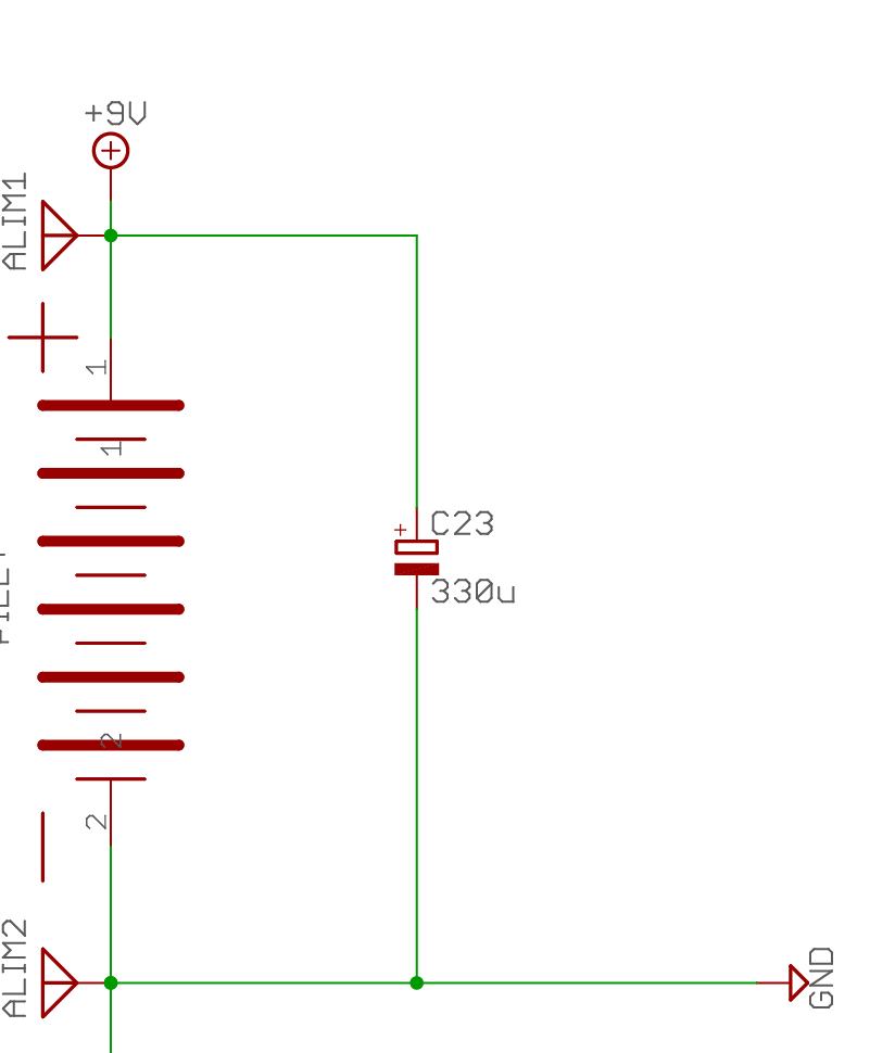
We encountered several problems with the oscillators, most of which had to do with keeping the signal clean and stable. For example, the impedance of the signal generated by the oscillator was too weak and multiplying it would distort the output signal, so we added a resistor to increase the impedance. Moreover, the VDD and GND was retroactively affected by the oscillators since the signal is of high frequency. Indeed, the oscillator decreased the voltage of VDD and increased the voltage of GND through voltage spikes. So, we added a decoupling capacitor between VDD and GND to absorb the voltage variations. We should’ve put a diode as well to block the current going back from the oscillator.
Managing the different actors
Once the circuit was designed, we printed it on the PCB. We used Autodesk Eagle to design it and then our teacher made it into a PCB. We then pierced the holes to put the components. Due to some unpredictable outcomes, we had to modify the PCB ourselves by soldering wires that could then be connected to other components.
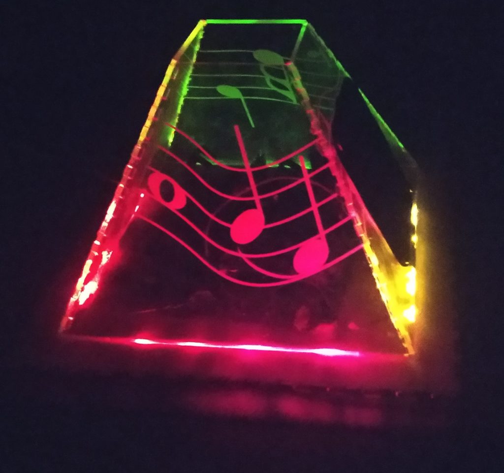
To build the prototype, we made a pyramidal box out of Plexiglas with a hole at the top in order for the time of flight sensor to sense the hand. One of the pyramid side has a hole at its center to put the speaker and another one has a hole to place the antenna. The STM32 is placed at the bottom of the pyramid. There is a wood box under the pyramid in which we placed LEDs to light up the pyramid at night, we also etched music notes on the faces so that they shine brighter compared to the rest of the pyramid.
Conclusion
It is to this day our most difficult project, not much because of its complexity, but mostly because of the precision we needed to achieve to make two clean oscillations that could survive being multiplied. We also had a hard time adapting the Cortex-M4 code to a Cortex-M3 processor because we never learned to access the register ourselves and modify the driver’s files.